| Quick Nav Bar | ||||||||
|---|---|---|---|---|---|---|---|---|
| << Previous | Contents |
Selection |
Op Index |
Parent | User Notes |
Index |
Glossary |
Next >> |
| a=RAYTRACE(ANTIALIAS, recursion levels, "tracepath","tracefile") [0==no antialiasing] |
| Items in CAPS are 0/1 switches or switches with more options than 0/1. |
![]()
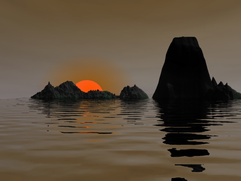
 Beginning with WinImages F/x R6, WinImages includes a very powerful ray tracing engine. The intent here is to provide a means to define some otherwise almost impossible to create effects at superior levels of quality to be further used within WinImages F/x.
You can map images onto spheres, create realistic looking water (and many other substances!), and much, much more with just a few lines of our easy to learn ray tracing language. You can also, with additional effort, define very complex objects indeed, such as the faceted, refractive gems we provide as one example of some fairly interesting objects.
We've provided control of many useful characteristics - reflectivity, refraction, transparency, roughness, and much more. You can "bump map" surfaces for a compelling look when you need an organic effect - waves are a good example of that. You can use image maps to give character to objects, and you can bump map those as well. If you use images that have active alpha channels in them, you'll be able to control the transparency of an object with the image map itself, which can lead to some amazing results.
In short, this is a very capable tool. While you can certainly use it for such relatively mundane tasks as wrapping an image onto a sphere in high quality, as the images on this page amply demonstrate, that's just the tip of the iceberg!
|
Ray tracing is an art; the more you use it, the better at it you'll get. If you're new to the idea, then take your time, look at the examples we've provided, and be prepared to spend many hours experimenting. Your investment in time will be well rewarded, we promise you.
WinImages F/x's ray tracing operation uses concepts that are common throughout the ray tracing community, so things you learn here will also apply to other programs in various ways. We look forward to seeing some of your creations!
|
For those of you new to Ray Tracing, we suggest you refer to our Ray Tracing Tutorial, where we provide an overview and some examples to get you started.
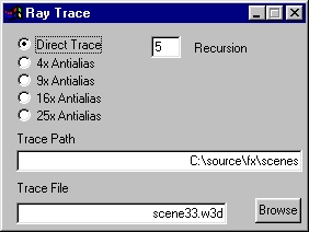
Anitaliasing
This set of radio buttons allows you to control the quality of the ray tracing operation. Direct Trace is fastest, and 25x Antialiasing provides the highest quality. It is best to design in Direct mode, then set the desired final quality. Image improvement beyond 4x anitaliasing is progressively more subtle; don't assume you need a high degree of antialiasing for every image - it simply isn't true.
Trace File
This selects the Trace File that controls the scene to be traced. The trace file contains a script that describes the objects in the scene, the lighting for the scene, and any animated parameters for the scene. Trace files are written using SceneScript; see below for details.
This may be edited manually or by using the browse button.
Trace Path
This selects the directory where the trace file exists on your computer.
This may be edited manually or by using the browse button.
|
Recursion
This controls how many times a light ray bounces from surface to surface. More levels results in increasing realism in the scene, particularly where transparent and refractive objects are encountered. Fewer levels result in higher speed. So, like the Anitialiasing setting, design with a low setting, and use a high setting for final quality work.
These scene files use a straightforward language called SceneScript that allows you to do anything from a very simple job to some enormously complex ones. What you create, of course, is up to you!
Most importantly, SceneScript is designed to be human-readable. While automated generation of SceneScript files was certainly part of the design goal, SceneScript files were also, in keeping with the design philosophy of all of WinImages F/x's other various control files, designed to be directly editable by you. For now, hand-written SceneScript files are the basis for all ray tracing using this operator. However, we do have another product, a separate 3D object editor, in development as R6 is being released. This will generate SceneScript files directly, and it is our intent to make it available to WinImages F/x users as soon as possible. Keep an eye on http://www.blackbeltsystems.com/ for news on this and other exciting developments.
Here's how scene files work. SceneScript files are processed first line first, last line last. For the most part, any setting or value you create remains set until set otherwise. So if you do this:
Then the effective color is 1,0,1, which is magenta, rather than 1,1,1, which is white. There is only one effective color at any one point in the SceneScript language stream.
This allows you to set up common elements of a scene, or part of a scene, first, and then they will be inherited just that way until you specifically change them.
This behaviour also allows you to use a group of settings (called a "trait") that are almost what you want, and then over-ride the elements that don't suit the needs of the moment. For instance, if you built a trait for water, you might set the color to blue as part of the trait. But perhaps today you're doing green water� so you use the trait normally, then right after applying it, you set the color to green, something like this:
SceneScript follows a very flexible format. Items inside angle brackets (< and >) are considered items to be interpreted. Anything outside these brackets is completely ignored. That allows you to place commentary anywhere in any SceneScript file, which will be very helpful, we assure you.
Any amount of whitespace (blank lines, tabs, spaces) can appear anywhere outside of a language element, and they can appear within language elements wherever a space is shown in the language reference. For instance, the following two lines both work fine, just the same way:
If a language element is not understood, it will be ignored.
When a language element requires more than one parameter, any that are left out are either set to zero (if they are numbers) or set to an empty string if they are text items. Generally, you should try to provide all parameters to keep from causing confusion.
SceneScript also has extensive, very easily managed provisions for animation of objects. Using the
| Language Element | Purpose | ||||||||||||||||||||||||||||||||||||||||||||||||||||||||||||
|---|---|---|---|---|---|---|---|---|---|---|---|---|---|---|---|---|---|---|---|---|---|---|---|---|---|---|---|---|---|---|---|---|---|---|---|---|---|---|---|---|---|---|---|---|---|---|---|---|---|---|---|---|---|---|---|---|---|---|---|---|---|
This language element may be used inside a |
EXP may range from 0.0 to 1.0. It represents the amount of light that is applied to an object when no light source directly shines upon that object. Another way to look at this is it means that this amount of illumination will apply to the object even when there are no lights. Use this term for the amount of illumination you want in shadowed areas of objects. The ambient amount is added to other light sources. | ||||||||||||||||||||||||||||||||||||||||||||||||||||||||||||
This language element may be used inside a |
EXP may range from 0.0 to 1.0. Note that a value of 0.0 is a special case that disables the feature.
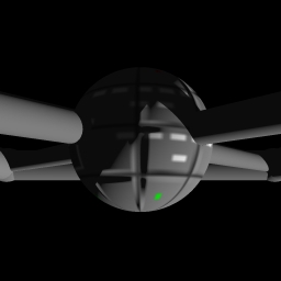
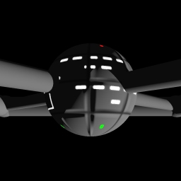
To explain the use of this, imagine the following situation:
You want to render windows on the station, some of which you desire to appear to be illuminated. These are placed on the bitmap texture for the station, along with other surface details. On the dark side, then, the windows should show brightly, though the rest of the surface texture is in the dark. However, under normal circumstances, with the ambient term set low, as these pass into the shadowed side, they darken with everything else.
Enter the
When you render the space station, those windows will glow just as brightly as they pass around the shadow side, while the rest of the surface detail, which is below the threshold, renders in shadow normally. The example images here make the benefits in this situation very plain. This technique applies to any apparent self-lighting issue; office buildings, fireflies, spaceships, pilot lights on control panels, etc.
|
||||||||||||||||||||||||||||||||||||||||||||||||||||||||||||
|
This allows you to apply any named trait. A trait is defined by surrounding one or more language elements with the tags
To use all of these characteristics just like this, you would place the following in your scene: This is the same as writing those characteristics out the longer way, but easier to look at and understand. |
|||||||||||||||||||||||||||||||||||||||||||||||||||||||||||||
|
IOR (EXP) can reasonably vary from about 1.0 on upwards.
IOR stands for "Index Of Refraction" and represents a controlling element for how much a light ray will bend when it transits the interface between the atmosphere and objects that have a differing IOR. This setting is related to the
|
|||||||||||||||||||||||||||||||||||||||||||||||||||||||||||||
This language element may be used inside a |
Each of X, Y and Z may be an expression.
The This means you can do things like this:
Within the above axis commands, you could place spheres, apply rotation commands, and use the
The
This language element is also used in conjunction with the 3d Here is an example of proper use:
| ||||||||||||||||||||||||||||||||||||||||||||||||||||||||||||
This language element may be used inside a |
Used with the |
||||||||||||||||||||||||||||||||||||||||||||||||||||||||||||
This language element may be used inside a |
Brilliance enhances the effect of light as it nears a direct reflection. This tends to produce "hot spots." EXP might reasonably range from 1 to 50 or so, with 1 being the kind of result you'd want for a matte surface, and 30 being a very "hot" reflective hot spot as light hits the object and bounces almost straight back. Below 1, unrealistic optical effects occur. | ||||||||||||||||||||||||||||||||||||||||||||||||||||||||||||
This language element may be used inside a |
Both X and Y may be EXP.
This statement allows you to tile a bumpmap texture 2 or more times across an object. The default situtation is once each way. The X and Y tilings are independent.
See also the
|
||||||||||||||||||||||||||||||||||||||||||||||||||||||||||||
This language element may be used inside a |
EXP may range from 0 to anything you like. Useful settings will depend on the values in the bump maps you're using. If the bump map goes from 0 to 255 (in other words, if the full dynamic range of a greyscale bump map is utilized,) then useful values will normally be in the 1 to 100 range. Your milage may vary! See also the |
||||||||||||||||||||||||||||||||||||||||||||||||||||||||||||
This language element may be used inside a |
This allows you to specify an image already loaded (or to be loaded) into WinImages F/x that will be used to disturb the apparent surface angle of any object that it is attached to. For IMAGEFILE, the complete path and filename must be specified. If the image is already loaded within WinImages F/x, then it will be used from there. If not, it will be loaded and then used.
If you specify the explicit "source" command instead of an image file, the currently assigned source image will be used as the bump map. An additional benefit of this approach is that in the timeline, you can use an animation as the source input to the raytrace operator, thereby allowing you to use an animated image as a bump map. Using WinImages F/x's "Save Project" menu item in the File Menu in conjunction with the various types of image maps can very useful, because it saves the settings of all the effects, as well as saving all images that were loaded when you use "Save Project." You can then later use "Load Project" to immediately load all of the components of a ray tracing project, including all image and bump maps. Images that are not loaded at trace time will be automatically loaded, however.
See also the
|
||||||||||||||||||||||||||||||||||||||||||||||||||||||||||||
This language element may be used inside a |
Each of X and Y may be an EXP.
This allows you to scale a bumpmap as it is applied to an object such as a rect using the |
||||||||||||||||||||||||||||||||||||||||||||||||||||||||||||
This language element may be used inside a |
Each of R, G and B may be an EXP.
Sets the full-object color (using Parameters are: R=0.0 to 1.0, G=0.0 to 1.0, B=0.0 to 1.0 Here are some reference colors for you:
|
||||||||||||||||||||||||||||||||||||||||||||||||||||||||||||
This language element may be used inside a |
Each of R, G and B may be an EXP.
Sets the color of vertex 0 of triangles until the next color0 statement. Also used in Parameters are: R=0.0 to 1.0, G=0.0 to 1.0, B=0.0 to 1.0 Here are some reference colors for you:
|
||||||||||||||||||||||||||||||||||||||||||||||||||||||||||||
This language element may be used inside a |
Each of R, G and B may be an EXP.
Sets the color of vertex 1 of triangles until the next color1 statement. Also used in Parameters are: R=0.0 to 1.0, G=0.0 to 1.0, B=0.0 to 1.0 Here are some reference colors for you:
|
||||||||||||||||||||||||||||||||||||||||||||||||||||||||||||
This language element may be used inside a |
Each of R, G and B may be an EXP.
Sets the color of vertex 2 of triangles until the next color2 statement. Also used in Parameters are: R=0.0 to 1.0, G=0.0 to 1.0, B=0.0 to 1.0 Here are some reference colors for you:
|
||||||||||||||||||||||||||||||||||||||||||||||||||||||||||||
This language element may be used inside a |
Each of R, G and B may be an EXP.
Sets the color of ghost color0 for the Parameters are: R=0.0 to 1.0, G=0.0 to 1.0, B=0.0 to 1.0 Here are some reference colors for you:
|
||||||||||||||||||||||||||||||||||||||||||||||||||||||||||||
This language element may be used inside a |
Each of R, G and B may be an EXP.
Sets the color of ghost color1 for the Parameters are: R=0.0 to 1.0, G=0.0 to 1.0, B=0.0 to 1.0 Here are some reference colors for you:
|
||||||||||||||||||||||||||||||||||||||||||||||||||||||||||||
This language element may be used inside a |
Each of R, G and B may be an EXP.
Sets the color of ghost color2 for the Parameters are: R=0.0 to 1.0, G=0.0 to 1.0, B=0.0 to 1.0 Here are some reference colors for you:
|
||||||||||||||||||||||||||||||||||||||||||||||||||||||||||||
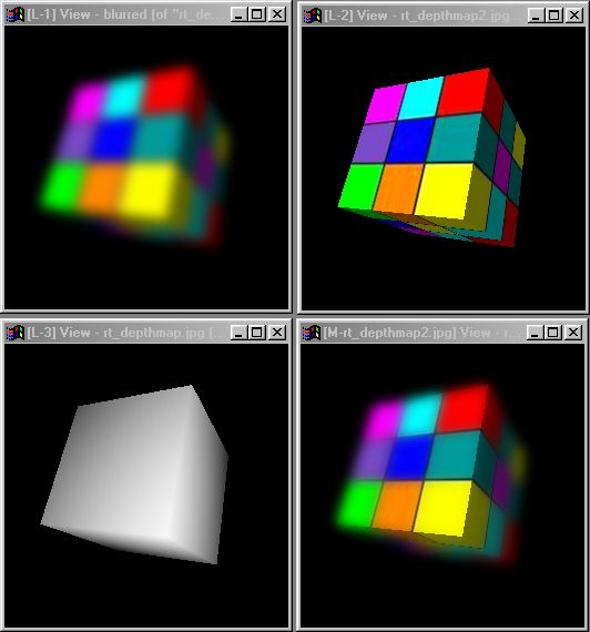
|
MIN and MAX may be EXP. EXP can be any distance from the eyepoint.
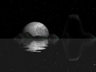
This statement changes the output of the raytracer from a realistic scene to one that is white where the scene's objects are closer than MIN, black where objects are more distant than MAX, and a grey value in between.
If both MIN and MAX are the same value, then the scene will be analyzed for the minimum and maximum object depth, and the greyscale result will reflect those as the MIN and MAX values. This doesn't work well for animations, because objects that move can change the effective depth of the scene. Example output: 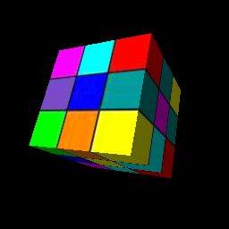 Normally traced object
|
|||||||||||||||||||||||||||||||||||||||||||||||||||||||||||||
This language element may be used inside a |
EXP controls how much an object responds to direct lighting. Its effect is modified by the |
||||||||||||||||||||||||||||||||||||||||||||||||||||||||||||
This language element may be used inside a |
T is a quoted name for a decision mapping method. P1, P2 and P2 may be EXP.
Decision mapping allows you to use a decision metric (such as a checkerboard) to decide whether to apply the
For instance, you can set up The following decision maps are supported:
|
||||||||||||||||||||||||||||||||||||||||||||||||||||||||||||
| Expressions |
Anywhere in a SceneScript file, an algebraic expression may be used where EXP is called for. Expressions may be simply a number or a variable name...
3.225 Or they may be a compound mathematics expression, denoted by an initial exclamation point:
!2+2
Compound expressions may contain one or more numbers and/or one or more variables (see the Variables must be defined prior to use; otherwise, they evaluate to zero. Expressions may not contain any whitespace at all, no exceptions whatesoever; in other words, this is legal... !sin(3+sqrt(rad(2.5))) ...but none of the following are legal:
!sin( 3+sqrt(rad(2.5))) Compound expressions are evaluated in this order:
Here are some examples, using the Y value of translate command and two example variables defined using the
Aside from these arbitrary examples, let's go through one where the need for a compound expression is clear.
Imagine you have a cylinder that you want to be part of a model of a space station. You're going to use this in four places; as four "spokes" that lead to the rim of the station. Accordingly, you need to rotate instances of the cylinder into the correct positions for the four spokes. So far, so good - that's easily done with the You could render a single frame with appropriate set of 90 degree values, and it would look fine.
Now consider the idea of animating the station. We want to make it spin around the same axis that the cylinders are defined around. But you already are using the Here's the solution (and it's easy): Instead of this, which specifies a single non-moving rotation of 90 degrees for a cylinder: Use this...
...which gives you the constant 90 degree offset you need, and adds the animated rotation value to that. The cylinder is initially oriented by the 90 degree term, and rotated appropriately by the variable yrot. Nice, eh? Available functions for use in compound expressions include:
|
||||||||||||||||||||||||||||||||||||||||||||||||||||||||||||
This language element may be used inside a |
This allows you to specify an image already loaded (or to be loaded) into WinImages F/x that will be used to supply the coloration of any object that it is attached to.
For IMAGEFILE, the complete path and filename must be specified. If the image is already loaded within WinImages F/x, then it will be used from there. If not, it will be loaded and then used. If you specify the literal parameter "source" instead of a complete path and filename, then the currently assigned source image will be used as the image map, instead of a file being loaded from an image. An additional benefit of this approach is that in the timeline, you can use an animation as the source input to the raytrace operator, thereby allowing you to use an animated image as an image map. Using WinImages F/x's "Save Project" menu item in the File Menu can be very useful, because it saves the settings of all the effects, as well as saving all images that were loaded when you use "Save Project." You can then later use "Load Project" to immediately load all of the components of a ray tracing project, including all image and bump maps, as long as they were loaded at the time you saved the project. The ray trace command will load required images automatically if they are not already loaded at execution time. Images used for imagemaps may contain alpha channel information (use TRIM, Targa, and TIFF files to save images with alpha information.) If they do contain alpha information, then the transparency of the alpha channel is applied to the object, which can be very useful.
See also the
|
||||||||||||||||||||||||||||||||||||||||||||||||||||||||||||
This language element may be used inside a |
Each of X and Y may be an EXP.
This allows you to scale an image as it is applied to an object such as a rect using the |
||||||||||||||||||||||||||||||||||||||||||||||||||||||||||||
|
"name" is required. A, B and the optional C,D... E,F... pairs may be EXP.
The
Values are pairs: A, a frame number (this is treated as an integer value), followed by a B, a floating point numeric parameter. Note that expressions are allowed in
Ideally, you would know the exact length of the animation you plan, and set the keys up for the exact frames you want. However, this is not always possible (and there are other reasons why the keys might not be exact... such as needing to generate a shorter animation to see if the general motion is correct - a lot of time can be saved that way.) So WinImages F/x will check the framenumber in the last frame of each
You can put one or more values in a variable. Here is an example of a single value use by name. Note the specification of the frame where the value starts, followed by the value:
Here is an example of how to set up a linearly interpolated value with several keys designed specifically for a 120 frame animation:
Here is an example of the same keys, splined:
Both of the above examples set up a rotation parameter that slowly changes from 0 to 45 degrees from frame 0 to frame 60 (half way through the animation) and then changes from 45 degrees to 357 degrees in the last half of the animation, from frame 60 to frame 120. You might then use this in the scene as follows: Note the lack of quotes when using the keyframed variable; you only use quotes to define the variable. It is very important that you begin each keyframe set with frame 1, and if there are more than one key in the set, it is critical that the last key specifies the last frame of the animation. You can place keys anywhere in between, at any or all frames. Further detail on the automatic length corrections...
In the above example, which was designed for 120 frames, WinImages F/x can and will automatically rescale all the frame numbers when the actual sequence length in the program differs from the There is a fairly simple method you can use to explicity control frame numbers over a large number of keys statements; it is practical as long as there aren't a large number of key frames. Basically, instead of using a number to specify the frame numbers, you can use variables instead. For instance:
...sets up a 120 frame key with a keyed frame at 3/4ths. But so does this:
...with the benefit that when you change the "lastframe" and "tqframe" variables, the "yr" variable changes too. In the case where a number of parameters are being changed and keyed against the 3/4ths point and the first and last frames, this mechanism could be used to explicitly change the keyframe values for all keys involved. This in turn ensures that the calculations for the keys are precise at all times.
See also the
|
|||||||||||||||||||||||||||||||||||||||||||||||||||||||||||||
This language element may be used inside a |
This allows you to specify a file that contains useful definitions, such as textures or colors you commonly use. See also the |
||||||||||||||||||||||||||||||||||||||||||||||||||||||||||||
|
This allows you to specify a path where the scene file will "look" for library files. For instance, if your scene files are normally kept in:
c:\scenes\ ...and you have a scene file called "myscene.w3d", then the following language snippet illustrates reasonable usage:
Together, these work to build the full name:
"c:\scenes\myscene.w3d"
The benefit of using the
|
|||||||||||||||||||||||||||||||||||||||||||||||||||||||||||||
This language element may be used inside a |
The parameter is an integer, either 0 or 1.
This language element allows you to define an object as a light source; this means that you can put a light inside it, and the light will come through the object. This is useful for making suns, light bulbs, candles, panel lamps, any object that would emit light.
Normally, objects in the tracer block light - so for the special case where one is to emit light, you need to use |
||||||||||||||||||||||||||||||||||||||||||||||||||||||||||||
|
This is a shortcut language element that is exactly equivalent to:
A commonly encountered scenario is to build an object centered around zero, and then scale, rotate and translate it away. In order to build the next object around zero, a convenient method is to use
For instance, we provide a library file that contains a fair number of triangles that define a cut gem as a unit. These are defined around zero, so that once placed in the scene file, they may be placed anywhere using
Now, you don't have to use |
|||||||||||||||||||||||||||||||||||||||||||||||||||||||||||||
|
The
When placing triangles, an additional modifier may be placed after groups of such triangles: See the There are five types of objects you can place. Most have their own specialized geometric preconditions that must be set up before the object is placed. Here they are:
In simple terms, the objects you use to construct images are the triangle (tri), sphere, and rectangle (rect). You illuminate these with lights, and tell the raytracer where groups of objects (except lights - they don't need or use bounds) are with one (or more) bounds. Bounds are of special interest; you need at least one at the end of a scene file. You can use more than one. In many cases, you benefit from using more than one. A bound groups objects for the raytrace engine - in technical terms, it places them inside "bounding spheres." If objects that are grouped in a small region - such as all of the triangles that make up one of the gem library composite objects - have their own bound statement, the ray tracer will run much faster. This is because it knows that unless a light ray hits that bounding sphere, it doesn't need to consider the triangles for the gem at all. This is because they are inside the sphere. The number of mathematical operations per ray are greatly reduced by this approach.
Some ray tracers don't handle bounding - some handle it automatically. This one puts you in the driver's seat. If it's all magic to you, just put one So, as a simple example, to create a scene with one plain red rectangle, you could do this...
...and then follow it up with a light:
Objects (except bounds) follow the
|
|||||||||||||||||||||||||||||||||||||||||||||||||||||||||||||
This language element may be used inside a |
Each of X, Y and Z may be an EXP.
This sets the X, Y and Z center position for spheres. See also the |
||||||||||||||||||||||||||||||||||||||||||||||||||||||||||||
This language element may be used inside a |
EXP sets the radius for spheres. See also the |
||||||||||||||||||||||||||||||||||||||||||||||||||||||||||||
This language element may be used inside a |
EXP sets how reflective a surface is. 0.0 is not at all, and 1.0 is 100% reflective. | ||||||||||||||||||||||||||||||||||||||||||||||||||||||||||||
This language element may be used inside a |
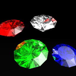
EXP represents an IOR that can reasonably vary from about 1.0 on upwards.
IOR stands for "Index Of Refraction" and represents a controlling element for how much a light ray will bend when it transits the interface between the object and the atmosphere, when the atmosphere (or another object contained within this one) has a differing IOR. The gems to the right demonstrate varying degrees of refraction and internal reflectivity to good effect. If you want to create transparency that does not refract - for instance, when you're using a texture with an alpha channel on a rectangle, and where it's clear, you want it to "dissapear" rather than act as a transparent substance - then just ensure that the IOR for the plane is the same as the IOR for the atmosphere and it'll work as you expect. If you have a differing IOR, it'll act like a clear material that refracts, instead.
This setting is related to the Here are some reference IOR values for your use:
|
||||||||||||||||||||||||||||||||||||||||||||||||||||||||||||
or This language element may be used inside a |
Each of X, Y and Z may be an EXP.
Each EXP sets the rotation for an When defined prior to the instantiation of an axis, like this...
...then the rotate command affects the
See also |
||||||||||||||||||||||||||||||||||||||||||||||||||||||||||||
This language element may be used inside a |
EXP can vary from 0 upwards. 0 is a very rough surface, and 100 is a comparatively smooth surface. This value is used in controlling how light reflects from a surface, especially as the light reflection approaches a direct (180 degree) reflection. For a highly polished object, use a large value. FOr a rough object where you want a large degree of diffusion of light, use a small value. | ||||||||||||||||||||||||||||||||||||||||||||||||||||||||||||
This language element may be used inside a |
Each of X, Y, Z and R may be an EXP.
This scales the objects or axis' that it is applied to. Set this first, then define the object(s). For most uses, objects should be defined around zero. Axis are scaled relative to parent axis, or to the world co-ordinate space if there is no parent axis. There are two ways to use this language element; in the XYZ form and the XYZR form.
The R parameter only applies in the case where the Examples:
See also |
||||||||||||||||||||||||||||||||||||||||||||||||||||||||||||
|
EXP may be an any number, however, it is evaluated as an integer, meaning that any fractional part has no effect on the random number generation.
This language element is used to "seed" the random number generator that underlies the texture engine. See the It is suggested you use this once, at the head of each scene script. This will ensure repeatable behaviour from the texture generator.
|
|||||||||||||||||||||||||||||||||||||||||||||||||||||||||||||
|
The Smoothing is done using a process related to bump-mapping; the geometric details of the triangles are not modified, only how light reflects off of them is. This means that the edges of objects seen in profile will retain the precise edges defined by the original set of triangles. Only surfaces that are not seen in profile will appear smoothed.
Keep in mind that the
|
|||||||||||||||||||||||||||||||||||||||||||||||||||||||||||||
This language element may be used inside a |
EXP sets the amount of light that "burns" to the light color near the highlight of an object. A value of 1 will result in a highly specular surface, while a value of 0 will result in no specular highlight display.
This works in conjunction with the
|
||||||||||||||||||||||||||||||||||||||||||||||||||||||||||||
This language element may be used inside a |
The parameter is an integer, either 0 or 1.
This turns splined variable interpolation on and off for use with the
|
||||||||||||||||||||||||||||||||||||||||||||||||||||||||||||
|
The
Typically, This is a classic "programming stack", in the sense that the first thing you push onto it will be the last thing pulled off. Here is the general concept:
Set up initial set of conditions
|
|||||||||||||||||||||||||||||||||||||||||||||||||||||||||||||
|
This term should be used before every group of objects that are conceptually one item; the group should then be followed by the To explain a little more, when you make a complex object that is to have the appearance and lighting behaviour of being solid, you construct it out of the relatively simple primitive objects the tracer can render: Triangles, spheres and rectangles. In the case of our faceted gem examples, the objects are made up of a fairly large number of triangles, placed and sized precisely where the faceted surfaces of a gemstone would be. Because refraction takes place when light transits from an objct of one IOR (index of refraction) to an object (or non-object) with a differing IOR, the tracer must know when light is entering and leaving a specific multi-primitive object in order to correctly adjust the light rays. In the case of these gems, light can enter the object through a facet and it can exit the object though a facet; in both instances, the IOR is known to change, so the light ray is bent (refracted) appropriately. It is entirely possible for an object to have internal structures of the same (or different) IOR and/or translucency; if that is the case, the renderer knows what to do based on which structure the objects belong to.
With all that in mind, the following shows how to use the
Remember: If you don't want light to bend, make sure you set the IOR of your objects to the same value as that of the atmosphere!
See also: The |
|||||||||||||||||||||||||||||||||||||||||||||||||||||||||||||
|
This term should be used after every group of objects that are conceptually one item.
See the |
|||||||||||||||||||||||||||||||||||||||||||||||||||||||||||||
This language element may be used inside a |
Each of P1, P2 and P3 may be an EXP.
The
The texturemap language element uses the three color statements ( In the following table, the suggested numbers are for a sphere of radius 4. As object sizes in the rendering space change, the textures may change as well, requiring readjustment of parameters. However, texture behaviour is independent of rendering resolution.
See also the
|
||||||||||||||||||||||||||||||||||||||||||||||||||||||||||||
This language element may be used inside a |
This statement is exactly like the
|
||||||||||||||||||||||||||||||||||||||||||||||||||||||||||||
This language element may be used inside a |
Both X and Y may be EXP.
This statement allows you to tile a bitmap texture 2 or more times across an object. The default situtation is once each way. The X and Y tilings are independent.
See also the
|
||||||||||||||||||||||||||||||||||||||||||||||||||||||||||||
|
This allows you define named traits. A trait is defined by surrounding one or more language elements with the tags
You can use this trait using the
The following language elements are recorded when used within a
* Each of X, Y, Z, R, G, B, P1, P2 and P3 may be an EXP.
|
|||||||||||||||||||||||||||||||||||||||||||||||||||||||||||||
|
See: |
|||||||||||||||||||||||||||||||||||||||||||||||||||||||||||||
This language element may be used inside a |
Each of X, Y and Z may be an EXP.
This moves an |
||||||||||||||||||||||||||||||||||||||||||||||||||||||||||||
This language element may be used inside a |
EXP describes the distance over which an object becomes opaque as a ray passes through it. Zero is a special case; when set to zero, translucency is not evaluated (the object is perfectly clear if transparent.)
If you have a sphere of radius 1, then setting translucency to 2 (the distance of the diameter) is equivalent to saying that the sphere is opaque when viewed through the center, and more transparent towards the edges. You should keep in mind that when an object is translucent, but has a different index of refraction than the medium from which a ray enters and/or leaves it (EG, the atmosphere's IOR is 1.0 and the sphere's is 1.5) then the rays warp around inside the object and take longer paths, so the translucency of the object becomes a great deal more apparent. Translucency has interesting effects inside objects that involve multiple internal reflections, such as a faceted gem. A significant amount of translucency will cause the gem to become darker along long reflective paths; the net result is typically that the edges appear clear and show the sparkle that one would expect, but that the deeper view into the gem darkens. This is exactly how most gems behave in real life - only the very finest of colored gems exhibit extreme clarity. This is why extremely clear rubies and emeralds can be worth more than diamonds by carat weight.
See also: Language elements
|
||||||||||||||||||||||||||||||||||||||||||||||||||||||||||||
This language element may be used inside a |
EXP sets an object's transparency. 0.0 is fully opaque, and 1.0 is fully transparent.
When an object is partially transparent, the color of the object (or the color of the image map at the relevant point on the object) "filters" the color of the light rays. One lurking "gotcha" is if you make a plane, bump map it (for water, for instance) and make it reflective, it'll work fine... but then, if you make it transparent - at all - sometimes it will turn completely black. Why? Because the color of the plane is black, and that's what filters the light. The solution is to simply make the color of the plane white ( |
||||||||||||||||||||||||||||||||||||||||||||||||||||||||||||
|
This language element is used to recover information that has been stored on the stack using the
Available synonyms for
See the
|
|||||||||||||||||||||||||||||||||||||||||||||||||||||||||||||
This language element may be used inside a |
T is a quoted name for the uvmapping technique. P1, P2 and P3 may be EXP].
The following UV textures are available:
|
||||||||||||||||||||||||||||||||||||||||||||||||||||||||||||
|
X, Y and Z may be EXP.
See also the
|
|||||||||||||||||||||||||||||||||||||||||||||||||||||||||||||
|
X, Y and Z may be EXP.
See also the
|
|||||||||||||||||||||||||||||||||||||||||||||||||||||||||||||
This language element may be used inside a |
Each of X, Y and Z may be an EXP.
Sets the X, Y and Z positions for the first vertex of a triangle.
See also |
||||||||||||||||||||||||||||||||||||||||||||||||||||||||||||
This language element may be used inside a |
Each of X, Y and Z may be an EXP.
Sets the X, Y and Z positions for the second vertex of a triangle.
See also |
||||||||||||||||||||||||||||||||||||||||||||||||||||||||||||
This language element may be used inside a |
Each of X, Y and Z may be an EXP.
Sets the X, Y and Z positions for the third vertex of a triangle. See also |
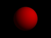
A Red Ball
|
Scene file for WinImages R6 Author - Ben Blish For Black Belt Systems January 2nd ... / 2000
Normally, we'd just include this trait from the library, but as an example, we'll just put it right here in the trace file:
This sets up rotation, scaling and translation as "off":
Here is the object we're going to trace:
Matte ball:
And here is the light that makes it show up!
Light:
|
Tri-Color Triangle
|
Scene file for WinImages R6 Author - Ben Blish For Black Belt Systems January 2nd ... / 2000
Tri-color triangle:
|
More Example Files
The W3D Sample Pages for basic W3D files you'll find useful.
Conversion Utilities
The 3D Exploration product, which can convert many 3D file formats to W3D.
The RAW Triangle to W3D Utility Converter
| Quick Nav Bar | ||||||||
|---|---|---|---|---|---|---|---|---|
| << Previous | Contents |
Selection |
Op Index |
Parent | User Notes |
Index |
Glossary |
Next >> |
| WinImages F/x Manual Version 7, Revision 5, Level B |
 You're rendering a space station. On the one side, it is illuminated by the sun. On the other, it is very dark, being entirely in shadow. This is accomplished by setting the ambient term for the object to a low value.
 Draw the texture with the surface details using colors that are no more than (for instance) 75% brightness, or 192 in decimal or C0 in hex. Where you draw the windows, draw them in a color that is fully "on", such as full white (1 1 1 / 255 255 255 / FF FF FF) or yellowish (1 1 .5 / 255 255 127 / FF FF 7F). Now use
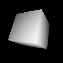
 Note that indentation shown is a matter of personal style; the author likes to flush objects left as shown here so there is a visual cue when the preceeding characteristics are instantiated in a specific object. Anything that works for you is fine, of course. Remember that if something isn't within a pair of angle brackets, the ray tracer ignores it.
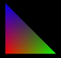 This simple scene demonstrates how to use the color0, color1 and color2 elements with a triangle. Note that there is no light - we don't need one, because right after applying matte, I turned up the ambient to 1, so the object is essentially lit by magic photons from the beginning of the universe, when WinImages was just a knot of cosmic string, waiting to... never mind. :-)