| Quick Nav Bar | ||||||||
|---|---|---|---|---|---|---|---|---|
| << Previous | Contents |
Selection |
Op Index |
Parent | User Notes |
Index |
Glossary |
Next >> |
| a=PARTICLES("root:\path\filename.psy") |
| Items in CAPS are 0/1 switches or switches with more options than 0/1. |
![]()
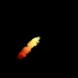
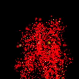
You can click on the images below to see how these systems can look in animated form. Note that there are many variations on system presentation based upon the area selections you use to generate the system, and these animations represent only single possibilities. For instance, the lava particle system's initial particle distribution is lathed from an area selection; in the still image below, that's a large ellipse. In the animation, we used the "stars" I-Shape and the result is completely different.
|
||||
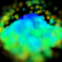 Galactic Funky Cloud |
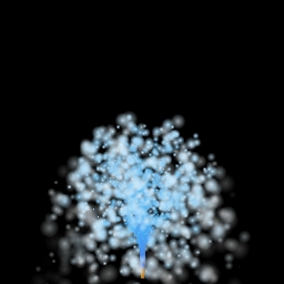 Water Fountain |
|||
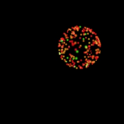 Fireworks |
 Rocket Exhaust |
|||
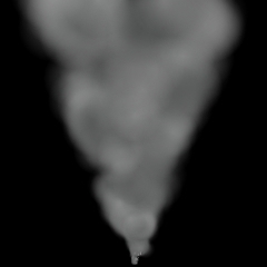
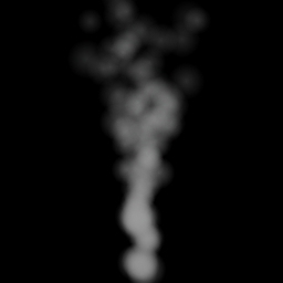 Smoke |
 Lava |
|||
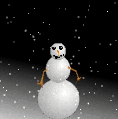 Snow (hey, we just had to make a snowman!) |
 Tornadic Vortex |
|||
The name of the particle system will be saved when dragged into the timeline, this means that different particle systems can be used at different frames in the timeline.
|
You have control over:
As you might imagine, creating an operator that can do all of the above - and a lot more - and keeping the operator complexity down to a reasonable level, was quite a challenge. We tried very hard to keep the complexity down to a dull roar, and as of this writing, we think we succeeded. While you may find (and we agree) that initially, this operator is very imposing, we think that it is understandable without an unreasonable amount of effort, and that it is also well worth putting forth that effort.
Now that we have the "pep talk" out of the way, let's dig into the operator itself. We'll begin with describing how WinImages's particle systems are structured and maintained so you have a good overview to fit the control specifics into.
Units of Measure
The very first thing to work your mind around is the idea that all particle system parameters are in the form of a floating point number from zero to one, with the single exception of the particle size, which is specified in pixels instead.
Why? Since particle systems are meant to be animated, generally speaking, the numbers 0.0 to 1.0 in time mean, from frame 0 to Frame N. So if you have a 32 frame timeline, .5 means about frame 16, and one means frame 32. If you have a 100 frame timeline, .5 means frame 50 and one means 100. Zero, naturally enough, means frame zero no matter the timeline size. And so on. In this way, any particle system design can fit itself to any timeline length automatically. That's really useful for quickly changing between test and production versions of a particle system. As far as the system is concerned, the only difference between a 100 frame timeline and a 10 frame timeline is it develops smaller steps per frame - but it is always the same results, within the limits of the time slices, of course..
And the exception to the rule? The reason that the pixel sizes are in "real numbers" is because you need very precise control of pixel size for most applications, and it's a lot easier to relate pixels to a real-world image than it is some fraction of that same image's size. Or so we thought when we designed it that way. Please do feel free to let us know what you think, if you disagree. Just shoot your opinion to us using this link:
System Composition
There are a two basic separate parts to a particle system, as follows:
The color palette is simple enough - it acts just like every other palette in the program. The interesting (and creative!) part is how the colors are used in a particle system, and we'll get to that later on. For now, it's enough to know that it's "just a palette," and that you need to specify one for every particle system.
The Particle System itself is maintained in a .psy file in your computer's filesystem. Inside the file are all parameters for the particle system except the coloration, which is in the .pal file previously mentioned; however, the name of the palette file is kept in the .psy file.
The Particle System itself has these components:
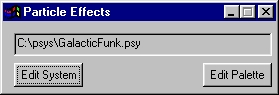
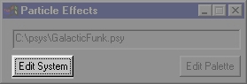
To create a particle system, you begin by pressing Edit System in the deceptively simple operator dialog:
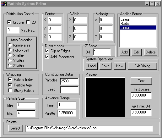
The Particle System Particle Editing Controls will open. It will attempt to open the particle system named in the main dialog; if it can't, it will complain about not being able to open (that message is coming from the palette loader... no palette is specified as yet, and that causes the message.) You can now load a particle system (such as the examples we supply) or you can define your own. To do that, you:
Work through each section of the dialog, designing where the particles are initially, if they're moving, how area selections affect the initial distribution, how the palette is applied over time, and what size they are. You also need to select a palette to be used to color the particles.
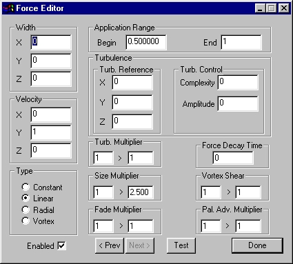
Once you have the initial situation set up, you add one or more forces to the particle system. To do this, you'll use the force editor, which is invoked from the upper right hand corner of the main Particle System dialog.
Now you would save the system - if you don't save, all your work will be lost when you press Exit Dialog!
Once you have the system saved, you can begin to test the system. There is a preview pane in the Particle System dialog with a Time setting so you can choose any moment in time (from 0 to 1.0) to see how the system looks. You can also scale the particles to fit the pane, which can be handy.
Essentially, particles are defined in an initial position, and then they move according to the forces that are applied to them. While they move, they have color and size changes applied to them. These relatively simple ideas really do sum up everything that goes on. Where it gets interesting is in the number of parameters that you have fine control over.
From here, we hope that between examining the sample systems we have provided and the control descriptions below, you'll get off to a running start. Good luck - and when you make something really cool, we want to hear about it:
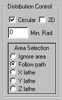
Distribution Control and Z Scale
The first thing to consider about any particle system is, how do you want the particles initially distributed? This area of the particle editor allows you to choose 2D or 3D initial distributions. One thing to keep in mind is that although you may have an initial width of zero on all three axis', the distribution is still in effect - and you'll see it as forces cause the particles to disperse from the initial point. So you always want to carefully consider (and probably try) both 2D and 3D distributions. Sometimes it makes quite a difference in the resulting system. Circular means that the particles either distribute in a disc or a sphere (2D or 3D.) If circular is not on, then the distribution is rectangular or cubic (again, 2D or 3D.)
![]() Z Scale also affects things when you have a 3D distribution; since there is no "real" Z-axis on a flat image (which we consider X-Y), you can get some interesting effects by using unusual elongation or compression of the Z-axis, which conceptually "goes into the screen of the monitor."
Z Scale also affects things when you have a 3D distribution; since there is no "real" Z-axis on a flat image (which we consider X-Y), you can get some interesting effects by using unusual elongation or compression of the Z-axis, which conceptually "goes into the screen of the monitor."
The Min Rad control allows you to force the particles out near the edge of the distribution. In the case of a circular (2D) distribution, a minimum radius of 0 means that the particles can be anywhere in the circle, and so you get an fairly evenly distributed disc of particles. But if you were to put .7 in the Min. Rad. control, then all the particles would be distributed between 70% and 100% of the outer edge of the circle, as the following two examples show:
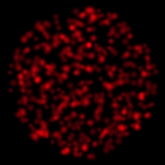 2D disc (0 Min Rad) |
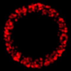 2D Ring (.7 Min Rad) |
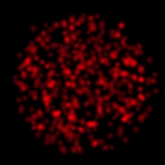 3D sphere (0 Min Rad) |
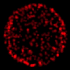 3D shell (.9 Min Rad) |
This works the same way with a 3D distribution, instead of a solid circle of particles, you get a hollow sphere of them.
The Area Selection portion of the Distribution Control area allows you to choose how WinImages F/x's various area tools affect the initial particle distribution. Keep that "initial" in mind. Once the particles are initially placed, the forces completely control where they go!
Ignore Area means just what it says. The only factors controlling the initial placement of the particles are the Center and Width parameters in this dialog.
Follow Path means that when you stroke a path (open or closed) using any of the stroking area tools, the particles are initially laid along that path.
When executing a Test Preview in Follow Path mode, the path used in the preview pane is a spiral.
See also: Path Generating (stroking) Tools
X Lathe, Y Lathe and Z Lathe are interesting distributors. What happens is, you make an area selection using any tool. The area selection is laid across the particle system, and the particles are constrained to distribute only within the area selection. So a Z lathe cuts out a particle distribution along X and Y; a Y lathe cuts out a particle distribution along X and Z, and an X lathe cuts out a particle distribution along Z and Y. In this way, you can create almost any arbitrary shape, on any axis, for the particles to initiate from. A good example of a lathe is the Lava animation; that used the Stars I-Shape to Y-Lathe out those individual columns of lava on the X-Z axis'.
When executing a Test Preview, in any of the three Lathe modes, the lathe used in the preview pane is a Z-Lathe, an X-Y ellipse.
|
Center, Width, Velocity
 These values set the initial state of the particle system. You essentially position the center, expand the system from that center, and set it moving with a constant velocity. Even when the width is 0, 0, 0, keep in mind that the distribution has nothing to do with the original width; distribution controls how the particles will expand in space when forces are applied. Think of the particle system as being infinitely small, yet still rectangular, circular or radial. Width just makes it bigger than infinitely small...
Construction Detail
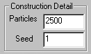 This area assigns initial parameters - how many particles there are, and what Seed to use to feed the random number system. This is important; the seed directly affects the distribution of the particles, and the Time Advance and Palette Advance distributions (more on these below.) If you change the seed, you'll get a different look for your system, though it will still generally conform to your design. Play with it to see what we mean. Another important idea is that the same seed will always produce the same sequences for any given system, assuming that you have the same values in it otherwise. Changing particle count will also strongly affect the random number system.
Particle Size
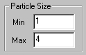 This simply assigns the initial size range for the particles. This range can be modified by forces, which can factor (or multiply) the size of each particle to be larger, or smaller using a number from 0.0 on up.
Advance Range
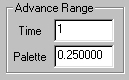 These are very interesting and useful controls. The term "advance", in the context of particles, means advanced in time. Time 0 is considered the initial state of the particle system. The system ends at time 1 - so at time 0.5, the system is halfway through its lifetime.
A time advance that is not zero means that when the particles are created, they will range from zero to the value in the time advance control. If you set a time advance of 1, then the particles will be evenly distributed from time zero to time 1, meaning that the system will have particles in all places the forces direct them to at all times. If you use a zero time advance, all of the particles will be in the intial position at time zero, and all will be at the end position at time one. Some examples are our fountain example. This uses a time advance of one so that the "water" is distributed evenly all along the fountain's normal path of activity. On the other hand, the fireworks uses a very small time advance (.1) to limit the particles to within 10% of where the forces say they should be at any point during the system's lifetime. You wouldn't want particles flying out of the system near the initial launch time - while with the fountain, since it's supposed to be continually operating, particles are in all positions at all times.
A palette advance works almost exactly like a time advance, but it advances the color used for the particle. If you have no palette advance (0.0), then the color of the particle taken from the palette will be at the top left for 0.0 time, and bottom right for 1.0 time. If you have a palette advance of .5, then particles at time 0 will have colors from the top left to the middle palette value. This interacts with the time advance, since that changes the age - it changes the color.
Wrapping
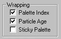 Now that we've covered time as it applies to a particle system's lifetime, it is appropriate to consider this: What happens to a particle at time one? This is an important question, because if you have any time advance at all, some particles will reach the end time of the system before otehrs do. Should they just sit there? Should they "go out"? Should they re-start at the beginning? Fade away? All are useful at times, and yes, all can be done. What particle Age does for you is take any particle that reaches time one, and changes it to time zero. In this way, a particle system can be completely cyclic, though you do need to consider the idea that if a particle is far from it's origin, it will "snap" to it's origin, dissapearing in an annoying fashion (that's where fading can be very useful... see the fountain example, and watch the particles fade away at the end of their fall. They're snapping back to the beginning at the bottom of the fountain, but they're invisible by the time they do so. Handy, eh?)
Palette Index does the same thing, but for color. Aged particles reach the end of the palette, and you have to decide if you want them to stay that ending color, or if you want them to restart at the beginning of the palette. If you check this, they re-start.
Sticky Palette interacts with time. If it is selected, the palette will stick to a particular particle, allowing you to create systems where any one particle is a particular color and will not change at any point.
Draw Modes
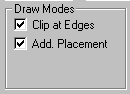 Clip at Edges means that particles "fall off" the edge of an image. If you're not clipping, the particles will come back in the opposite side of the image from the side they are moving off of. Deciding on this depends on what you're doing. For a fog, you'd want them to wrap around, perhaps, if the time wrapping wasn't handling it for you, which it can (think about it!) For an explosion, you definitely want particles that dissapear off the edge of the image to stay gone. If they came back in the other side, your viewer would be quite dissapointed with you!
Add. Placement means "Additive Placement". Instead of being drawn onto the image, the particles are added to it. This is a process that more closely mimics the behaviour of light; you might want to keep that in mind for explosions, fireworks and so forth, systems that are essentially systems of light emission.
Applied Forces
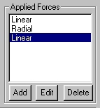 Here is where it really gets fun! This lists the forces that you have in your particle system. You can have any number of forces (we've only needed a maximum of four forces to do any of the demonstration systems we've provided, but if you need tens, or hundreds, or even thousands of forces, you can go ahead and set them up), you can have dormant (disabled) forces, and your forces can affect other things besides position - they can adjust transparency, turbulence, size, and even the palette advance. What you can do in this part of the particle system editor is add a new force, delete one, or edit one that is already there. Each force listed identifies itself by it's type, and notes if there is turbulence involved. Double-clicking on a force opens the
force editor, which you'll learn more about shortly. For the moment, just think of forces as things that apply to particles over time in various ways, modifying their characteristics and making them move.
Here is where it really gets fun! This lists the forces that you have in your particle system. You can have any number of forces (we've only needed a maximum of four forces to do any of the demonstration systems we've provided, but if you need tens, or hundreds, or even thousands of forces, you can go ahead and set them up), you can have dormant (disabled) forces, and your forces can affect other things besides position - they can adjust transparency, turbulence, size, and even the palette advance. What you can do in this part of the particle system editor is add a new force, delete one, or edit one that is already there. Each force listed identifies itself by it's type, and notes if there is turbulence involved. Double-clicking on a force opens the
force editor, which you'll learn more about shortly. For the moment, just think of forces as things that apply to particles over time in various ways, modifying their characteristics and making them move.
System Operations
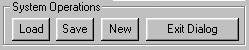 Here, you can load and save particle systems.
|
You can also clear the current system using the New control, and you can exit the dialog. Just save first!
Preview
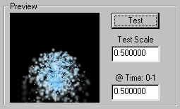 The preview area is a fast way to see if you're on the right track; the small window can display the particle system at any point in its lifespan. You set the particlar point by setting the @Time 0-1 control. You can also scale the particles so that the preview more closely represents what your final results will.
|
To view your system, press the Test control.
Palette
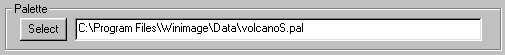
This area is used to select the palette you want to use for the particle system. You can hand-enter the path and filename if you know it, or you can use the Select button to navigate the file system using a standard dialog.
Application Range
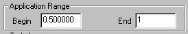 This pair of controls set the range of time in the systems 0.0 to 1.0 lifespan that this force is applied. Remember that 0.0 is the beginning of the system, thinking in terms of the timeline's first frame, and 1.0 is the end of the system, thinking in terms of the timeline's last frame. So 0.25 is 1/4 of the way through the timeline.
Force Decay Time
![]() The Force Decay Time control sets how long it takes for the applied velocity to "die out" after the application of the force ends. For instance, when you shoot a bullet, initially a very high amount of force is applied. But there is air resistance, and it directly opposes the bullet's forward motion. Eventually, that motion will be completely eliminated by the air. This parameter acts as the air in this idea; it specifies a time period after the force is done being applied that the force takes to decay to zero. If the force does not end (spans time from 0 to 1 in the system) then this has no effect. If it is set to 0, then the force does not decay at all. If it is set to a high value, decay is very slow and may not be apparent; if it is set to the remainder of the time between when the force ends and the system ends, the force will die out just as the system reaches time 1. For instance, if the force is specified from 0 to .6, and the decay is .4, that means that the veloocities imparted by the force will have reached 0 just as the system lifespan ends.
The Force Decay Time control sets how long it takes for the applied velocity to "die out" after the application of the force ends. For instance, when you shoot a bullet, initially a very high amount of force is applied. But there is air resistance, and it directly opposes the bullet's forward motion. Eventually, that motion will be completely eliminated by the air. This parameter acts as the air in this idea; it specifies a time period after the force is done being applied that the force takes to decay to zero. If the force does not end (spans time from 0 to 1 in the system) then this has no effect. If it is set to 0, then the force does not decay at all. If it is set to a high value, decay is very slow and may not be apparent; if it is set to the remainder of the time between when the force ends and the system ends, the force will die out just as the system reaches time 1. For instance, if the force is specified from 0 to .6, and the decay is .4, that means that the veloocities imparted by the force will have reached 0 just as the system lifespan ends.
Width
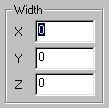 The Width controls allow a force to expand or contract the distribution area for a particle system on any combination of the X, Y and Z axis'.
Velocity
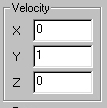 The Velocity controls allow a force to impart movement to a particle system on any combination of the X, Y and Z axis'. The type of movement depends on the Type field, described next. When these values are all set to zero, the force has no effect on the motion of the particle system, but can still affect it by carrying modifiers such as Size and Fading. More detail may be found about modifiers below.
Type and Vortex Shear
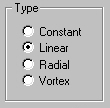 The Type controls determine if the energy imparted to the particle system will be:
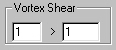 For Vortex motion, you can also use the Vortex Shear control to advance the vortex so that it represents a "twisting" motion rather than a circular motion.
Enabled
![]() The Enabled control, when checked, causes the force to be applied. If you uncheck it, the force is completely removed from the particle system calculations - it will be as if it wasn't there at all. This can be useful when you are testing a system that has many forces that interact, and you want to see just one at a time. Disable all but the ones you want to work with, adjust them, then turn the others back on. Also, at times you may have more than one set of motions defined; by using the Enable mechanism, you can control which ones are in effect for the instance you're working on at the moment.
The Enabled control, when checked, causes the force to be applied. If you uncheck it, the force is completely removed from the particle system calculations - it will be as if it wasn't there at all. This can be useful when you are testing a system that has many forces that interact, and you want to see just one at a time. Disable all but the ones you want to work with, adjust them, then turn the others back on. Also, at times you may have more than one set of motions defined; by using the Enable mechanism, you can control which ones are in effect for the instance you're working on at the moment.
Turbulence and Turb. Multiplier
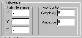 The Turbulence controls allow any force to carry a turbulent peturbation of the position (not the velocity) of the particles in the system. The X, Y and Z controls change the character of the turbulence; we sample turbulence out of a "turbulent space", and this changes where the sample is taken. You can leave this at 0, 0, 0 for most situations. If you don't like the way the turbulence looks, try other locations from 0 to 255 as a floating point number in these controls.
The Complexity control literally controls how complex a displacement is imparted by the applied turbulence. Smaller values (like .01) give reduced complexities, and larger values (like .1) give enhanced complexities.
 The Amplitude control is factored with the Turb. Multiplier control to determine the amount (as opposed to the complexity) of the turbulence. When the result of the factor is zero, there will be no turbulent displacement.
Size Multiplier
 The Size Multiplier control is a modifier. It is "carried" by a force, and factored onto the particle size. For it to have no effect, set both values to 1.0; this means that the size is multiplied by 1, and so is the same as it was. To enlarge, you can set a range from 0 to 1; that will go from very small to the full size specified in the particle system editor over the span of the force's application. Note each force contributes a factor. Forces that you don't want to change things should have both values set to 1.0.
Fade Multiplier
 The Fade Multiplier control is a modifier. It is factored onto the particle transparency. At 1.0, the particles are opaque. At 0.0, they are completely transparent. Each force factors all other currently active forces, so if you have two forces active that are applying .5 here, the result is:
You'll definitely want to kepe this in mind! To eliminate any effect in a particular force, set both values to 1.0.
Pal. Adv. Multiplier
 The Palette Advance Multiplier control is a modifier. It is "carried" by a force, and factored onto the particle's palette advance as set in the particle editing dialog. For it to have no effect, set both values to 1.0; this means that the advance is multiplied by 1, and so remains the same as it was. Note that each force contributes a factor. Forces that you don't want to change things should have both values set to 1.0.
Other Controls
![]() Done exits the dialog. The force settings are retained until you close the the particle system editing dialog - closing the force editor dialog does not discard any information. However, you must save the particle system before you exit the main particle system editor dialog, or all changes to all forces and the system itself are lost.
Done exits the dialog. The force settings are retained until you close the the particle system editing dialog - closing the force editor dialog does not discard any information. However, you must save the particle system before you exit the main particle system editor dialog, or all changes to all forces and the system itself are lost.
Test allows you to start a preview in the particle system dialog, just as the Test button in the that dialog does. This enables you to work on a force without going back and forth between the two dialogs.
Next and Prev step you through the forces that are available for this particle system.
| Quick Nav Bar | ||||||||
|---|---|---|---|---|---|---|---|---|
| << Previous | Contents |
Selection |
Op Index |
Parent | User Notes |
Index |
Glossary |
Next >> |
| WinImages F/x Manual Version 7, Revision 5, Level B |