|
|
|
|
|
|
|
|
|
|
|
|
|
|
|
|
|
|
|
|
|
(Click any button to go to the documentation for it)
| Quick Nav Bar | ||||||||
|---|---|---|---|---|---|---|---|---|
| << Previous | Contents |
Selection |
Op Index |
Parent | User Notes |
Index |
Glossary |
Next >> |
|
|
|
|
|
|
|
|
|
|
|
|
|
|
|
|
|
|
|
|
|
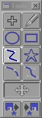
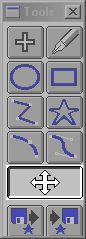
The Object Placement Tool Box contains nine separate tools used for specifying points, control lines, and control curves in a morph. Collectively, these are known as controls. controls allow you to specify sections of an image that should change into each other. For example, if you are morphing two faces, you would place controls around the eyes, nose, mouth, etc.
Morph offers a wide range of tools that include freehand lines, ovals, rectangles, polylines, splines, shapes, and bezier curves. Each of these tools can be used to place control lines on the start image, and then on the end image. An object placement method is selected by pressing the desired icon in the tool box. After you have done this, the selected mode will become current. This means that this mode will be used for all line or point placement until a new mode is selected.
The Left mouse is used to specify a point or the initial point of a line or curve. The left mouse button is also used for sizing ovals, rectangles, and IShapes. Each line mode has a little bit different use of the left button, so you should read each of those sections for more details. The right mouse button is used to move the entire control line or curve. The right mouse button is also used to signal morph when you are done drawing a polyline, spline, or bezier curve.
Each control object has a direction based orientation. For example, all ellipses are drawn clockwise from vertical. This means that the orientation of the object is clockwise from vertical. This is very important especially when you change from tool to tool. Let's say that you have drawn an oval in the start image, and would like to draw a freehand control line in the end image. The oval's orientation is always clockwise from vertical. This means that the line would need to be drawn from the top of the feature clockwise around it. If you were to draw the counter-clockwise from vertical the feature would become inverted over the sequence. You must always keep this in mind when specifying any lines. If you start to outline an eye in the start image from the top going counter-clockwise, then you must outline the eye or feature in the end image in the same manner - from the top going counter-clockwise.
Another important issue is the amount of lines to use for a particular morph. In most cases you will produce a better quality morph if you specify a series of short, specific lines, instead of one long line. This is due to the fact that long lines are less specific, and therefore tend to shift the position of the image data more than short lines. For example, let's say you are morphing a profiles, and would like to create a "Pinocchio Nose" effect over the sequence of frames. If you were to use one long line to specify the outline of the nose and face, you would see that the sequence would shift some image data from the forehead and lips into the area that should be the nose. This can be avoided by specifying shorter lines that outline each feature independent of the other lines. For this example you would specify a line for the forehead, the nose, the lips, and the chin. Remember, there is no limit to the number of lines that you can use. So, use lines and curves wherever you need them in your morphing sequence.
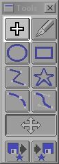
The Point tool allows you to specify single control points on the start or end image. Placing a point in one of the images (start or end) will automatically place the same point in the other image. The point will be placed in the exact same position in the other image. All points are specified by a single left mouse click. Once a point has been specified, you can "grab" or move the point by clicking on it with the right mouse button. Once the point is in the desired location, release the right mouse button. You can switch from point to point (object to object) by pressing the left and right arrow keys on the keyboard. Doing this will scroll you through each of the available point and line objects in the start and end images.
Points can be deleted by selecting the Delete button from the tool bar, or by pressing the Delete on the keyboard. Once a point or line is deleted, it can not be retrieved. In some cases the arrow keys may appear to not be working. This is because the input focus for the program has shifted from the image views to the filmstrip. If this occurs, simply click anywhere in the background to return the arrow controls to the image views.
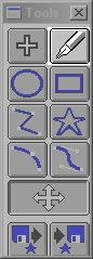
The freehand tool allows you to draw a free form area as a control line. The line is specified by holding down the left mouse button and drawing the desired region on the start or end image. After the freehand area is set to the desired shape, release the left mouse button. WinImages Morph will then wait for you to make a freehand control line in the other image. Once this has been completed, the specified lines will be drawn using the specified color and thickness values. The area can be repositioned by pressing both the left and right mouse buttons while drawing. After the freehand line is in the correct position you may continue drawing by releasing the right mouse button or finish drawing the line by releasing both buttons. Freehand lines can be placed in the exact same position in the other image by pressing the Enter key. This will simply drop the line into the other image using the same size and position information.
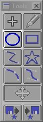
The oval tool allows you to draw an elliptical shape as a control line in the start or end image. The oval is sized using the left mouse button, and its position is manipulated by using both mouse buttons at the same time. Once the mouse buttons are released, morph will wait for you to make an elliptical line specification in the other image. Once both ovals have been placed in the images, morph will draw the lines using the specified color and thickness settings. An oval can be directly placed into the other image by pressing the Enter key. This will simply drop the elliptical line into the other image using the same size and position information.
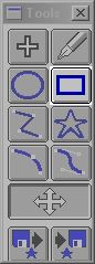
The rectangle tool allows you to select rectangular control lines. The rectangle is sized by pressing the left mouse button, and is moved by pressing both the left and right mouse buttons. Once the mouse buttons are released, morph will wait for a rectangle to be placed in the other image using he same method. After both rectangles have been placed, morph will draw the rectangle lines using the specified color and thickness settings. Rectangular lines can be placed in the exact same position in the other image by pressing the Enter key. This will simply drop the line into the other image using the same size and position information.
The polyline tool allows you to create lines between specified points. The left mouse button is used to specify all of the points except the final one. The polyline is completed by simply pressing the right mouse button after the final point has been specified. This will signal morph that you have finished drawing in the first image.
At this time, you can press the "ENTER" key and the object will drop in the other frame in the same relative position.
You also have the option to simply begin drawing in the other image once the first polyline is complete. In this case, instead of pressing "ENTER", use left clicks to place the line in the other image, and the a final right-click to lock the line down.
|
You may move the polyline at any time prior to completing it by pressing the left mousebutton, holding it and then pressing and holding the right mouse button also, and then dragging. Once you have repositioned the polyline, you may continue drawing sides or complete the shape.
Morph will automatically draw the lines using the specified color and thickness settings when the second line is completed.
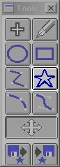
IShapes are custom lines ranging from the outline of North America to the skyline of London. The IShape Tool works like this:
WinImages Morph also gives you the ability to create your own custom IShapes. The procedure is extremely simple. First, outline the area that you wish to be an IShape using one of the area selection tools (preferably polyline or freehand). For example, if you wanted to create an IShape of a face, you would use the polyline tool to trace the around the face. After you have completed the shape, press the Save IShape icon in the Tool Box. After the Save IShape icon has been selected, you can then specify a name for your IShape, and where it is to be stored. You can then call your new IShape at any time by selecting the Load IShape icon, and specifying the proper name and path for the IShape.
IShapes can not be created from a point, a group of points, or links. IShapes can only be created using one of the provided line or curve drawing tools.
See Also:
Load IShape
Save IShape
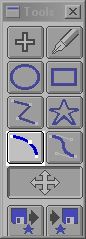
The Spline tool allows you to place curved lines on the start and end images. These curves are determined using a best fit curve between points. Points are specified using the left mouse button. If you press and hold the left mouse button, you will be able to visibly alter the curvature between the existing points. This curve can be altered on point at a time around to desired object. When specifying a point, it is important to remember that the desired curvature of the line is set at the same time. This means that you should click and hold the left mouse button down for each point. Then move the mouse until you find the desired line curvature. After the line is the proper length and curvature, release the left mouse button, and apply the next point. If this is the last point in the curve, right click after it has been positioned. This will signal morph that you have completed this curve, and will begin a new curve in the alternate view window. (Note: starting a new curve in the same window will eliminate the old curve.) After you have completed the second spline curve, press the right mouse button to complete the drawing. Morph will replace the outlines with the specified line color and thickness.
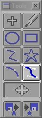
The Bezier Curves Tool allows you to place bezier based control curves on the start and end image. A Bezier curve is a tangential based spline curve. This means that the curve from point one to point three (see diagram below) is based on a tangent to the original line. Bezier curves have four separate control points. The initial position, the end position, and two middle curvature points. These two middle points determine the curvature between the initial and terminating points of the curve. Below is a step by step guide to using the bezier tool.
It is important to remember that the right mouse button can be used in conjunction with the left mouse button to move the entire curve. Pressing the right mouse button without the left pressed will signal morph that you are finished drawing the curve. You can then place the desired curve in the other image, or you can drop the curve into the other image by pressing the Enter key. If you continue to draw in an image view after the right mouse button has been pressed, you will be creating a new curve. The previous curve will be eliminated.
This area selection mode can be edited by selecting the Edit area selection icon from the area tool box. Once you are in edit mode, no new points may be added to the Bezier curve. You may only adjust the existing points position and the lines' curvature settings. If you drag a point you will simply be moving the points position which can effect the overall curvature of the line. If you would like to alter only that points curvature, press the CTRL key after right clicking on the desired point. This will allow you to alter the curvature of that point without eliminating the overall curvature of the entire line. If you would like to increase or decrease the curvature of an entire group of points, press the Shift key while editing the points. By doing this, you will be editing the whole curve while maintaining the overall curvature of the line. You also have the option of moving the curve while leaving the current points curvature angle. This means that only the angle at the initial point will remain the same, and the curvature of the rest of the line will be altered. The keystroke for this type of Bezier editing is CTRL and Shift after you have right clicked on the desired point.
The Move Object option allows you to resize or alter the position of a control point, line, or curve. Selecting the Move Object button from the Tool Box will place WinImages Morph into the move object mode. In this mode all control objects can be moved using the left and right mouse buttons. The Move Object tool is primarily used for resizing and editing an existing control object. All objects, except points, will have handles associated with them in this mode. A handle allows you to move and manipulate that section or portion of the line or curve. They can also control the curvature for spline and bezier curves. The left mouse button will always change the position of the current object handle. The right mouse button can be pressed over any of the handles to move the entire object. Releasing the right mouse button will drop the object. The arrow keys can be used to switch from object to object. As each control object is encountered morph will provide the appropriate handles for the object. When you have finished moving the desired objects, select any of the other tools to exit the move mode.
Pressing the Enter key with a freehand line selected will cause that line to change into a spline curve. In some cases a spline based curve is easier to manipulate than a freehand line. Once a line is converted it can not be changed back.
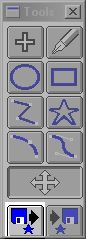
The Load an IShape tool allows you to select an IShape to be used with the IShape line placement mode. The IShapes range from stars to the outline of Australia. You may also load your own custom IShape creations. The IShape that you load will remain current even if you change object placement modes.
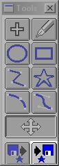
The Save an IShape function allows you to save altered or custom IShapes. After creating the IShape you can save it using this function. You can also create IShapes using one of the line specification modes. It is important to remember that this option will save the last line that was drawn. For example, if you were drawing the outline around a face on the start image, and then on the end image, the end image's line would be saved by this option. This process is described in greater detail in the section on the IShape line specification tool.
| Quick Nav Bar | ||||||||
|---|---|---|---|---|---|---|---|---|
| << Previous | Contents |
Selection |
Op Index |
Parent | User Notes |
Index |
Glossary |
Next >> |
| WinImages F/x Manual Version 7, Revision 5, Level B |