
| Quick Nav Bar | ||||||||
|---|---|---|---|---|---|---|---|---|
| << Previous | Contents |
Selection |
Op Index |
Parent | User Notes |
Index |
Glossary |
Next >> |
| a=CONTOUR(red, green, blue, b_red, b_green, b_blue, PLACE BACKCOLOR, interval, EDGE DETECTION) |
| Items in CAPS are 0/1 switches or switches with more options than 0/1. |
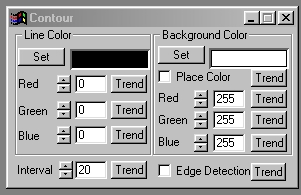
The Contour operation will outline areas of similar brightness in an image. These "contour levels" can be used to create effects ranging from contour mapped images to line art. You can control the spacing of the lines, their color, and the color of the background. The background color can be placed by selecting the Place Background option. The contour lines are placed based on areas of similar brightness in the image, and the Interval setting. The interval can be thought of as the luminance or brightness spacing between the contour lines. There are a total of 256 interval levels ranging from 1 to 256. The interval control is explained in greater detail below. An example image using the contour operation can be viewed below.
 Original Image |
 Contour, with Background color placement |
Trends
You will notice that all of the controls have a Trend button next to them. The trend button allows you to set that variable over a set of frames. Each frame of the animation can be thought of as a slice of time. The trends allow you to alter some, all, or none of the variables for a particular time slice. You will notice that the trend graphs have equidistantly spaced vertical lines. Each of these lines represents a frame in the animation. The number of frames can be altered using the Sequence controls... in the Time Line pull down menu. Animation lengths of 100 - 999 frames will be represented with a vertical bar being 10 frames, and animation length greater than 1000 frames will have a vertical bar for every 100 frames. Click here to view more information on Trends.
Contour Line Color Preview Window
This preview window will display the color of the line that is to appear in the selected area. This color will change as the Red, Green, and Blue values are altered. As the RGB controls are altered the contour line color preview will be updated to reflect the changes. Pressing the Set button allows you to access the Color Selection Dialog. This dialog can be used to specify a custom or named color as the contour line color. If you would like to learn more about the set color dialog, Click Here.
Red
This slide gadget allows you to specify the Red component of the RGB value for the Contour Line color. This value can be altered by adjusting the sliders or by entering the values. The values for any of the RGB components range from 0 to 255.
Green
This slide gadget allows you to specify the Green component of the RGB value for the Contour Line color. This value can be altered by adjusting the sliders or by entering the values. The values for any of the RGB components range from 0 to 255.
Blue
This slide gadget allows you to specify the Blue component of the RGB value for the Contour Line color. This value can be altered by adjusting the sliders or by entering the values. The values for any of the RGB components range from 0 to 255.
Background Color Preview Window
This preview window will display the color of the background color that is to appear between the contour lines. This color will change as the Red, Green, and Blue values are altered. As the RGB controls are altered the Background color preview will be updated to reflect the changes. Pressing the Set button allows you to access the Color Selection Dialog. This dialog can be used to specify a custom or named color as the background color. If you would like to learn more about the set color dialog, Click Here.
Place Background
The Place Background control allows you to insert the selected Background Color or to place the contour lines over the top of the existing image. Placing the background will fill the region between the lines with the background color. If this control is not selected, the original image will appear between the lines.
Red
This slide gadget allows you to specify the Red component of the RGB value for the Background color. This value can be altered by adjusting the sliders or by entering the values. The values for any of the RGB components range from 0 to 255.
Green
This slide gadget allows you to specify the Green component of the RGB value for the Background color. This value can be altered by adjusting the sliders or by entering the values. The values for any of the RGB components range from 0 to 255.
Blue
This slide gadget allows you to specify the Blue component of the RGB value for the Background color. This value can be altered by adjusting the sliders or by entering the values. The values for any of the RGB components range from 0 to 255.
Interval
The interval control allows you to specify the spacing of the contour lines on the image. The contour lines are placed based on the specified interval value, and the actual brightness values found in the image. The control ranges from an interval of 1 to an interval of 256. A setting of 1 means that each contour level in the image will have a line. This will result in the entire area selection being filled with the specified contour line color. An interval of 256 means that no contour lines will be placed in the selected area. Other interval settings will place contour lines based on their value, and the total number of intervals. For example, if you were to select an interval setting of 15, then there would be a contour line for the 15th, 30th, 45th, 60th, ... , and the 255th luminance level in the selected area. You can modify this effect by turning the Detect Edge option on. In that case, WinImages F/x will only place contour lines where edges with the same interval value are found. This will give you an image that contains fewer contour lines, and defines the edges in the image. The two methods are shown below. The image on the left is just a contour, and the image on the right is a contour with edge detection on.
 Original Image |
 Contour of 15 |
 Contour of 15 with Edge Detection |
Edge Detect
This control is used to change the method of placing contour lines on the image. If this option is selected, contour lines will only be placed on edges in the image where the luminance difference is equal to the interval value. This will eliminate contour lines in areas of the image that do not contain specific edges (brightness differences). If the control is not selected, then the contour lines will be placed at the specific interval setting. This option can be used to create "cleaner" line art, or to reduce the effect of the contour line operation.
| Quick Nav Bar | ||||||||
|---|---|---|---|---|---|---|---|---|
| << Previous | Contents |
Selection |
Op Index |
Parent | User Notes |
Index |
Glossary |
Next >> |
| WinImages F/x Manual Version 7, Revision 5, Level B |